|
by
|
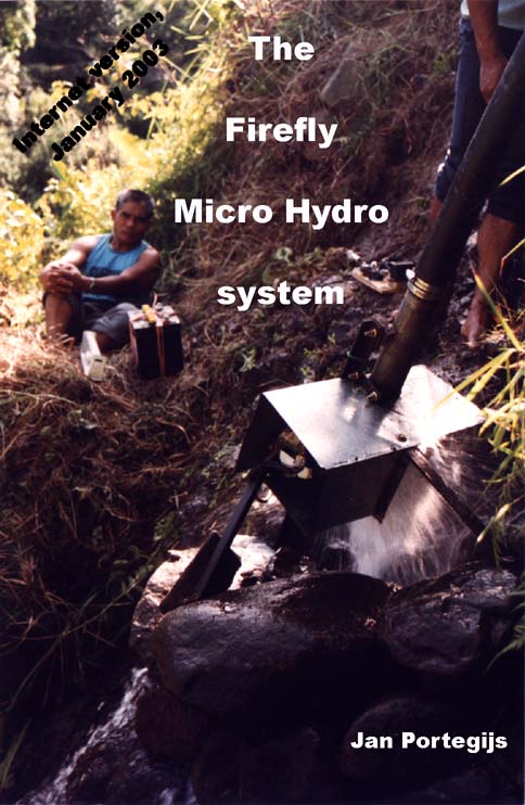 |
| Picture: The first time the prototype
charger was running at the site in pilot village Cambulo,
Banaue, Ifugao prov., Philippines. |
| 1.1 |
A real firefly.
It's an impressive sight to see thousands of them
twinkling in a tree on a moonless night. |
| 1.2 |
High school students
testing the charger they have built. The man
listening so attentively is their physics teacher. With
thanks to the Gouda firebrigade for lending them a pump. |
| 2.1 |
Typical layout of an
installed firefly charger, schematic drawing. |
| 2.2 |
The first prototype in
the workshop where it was built. There was no drill,
holes in the frame had to be cut using an electric arc
welding set at full blast. Covers are not fitted yet. |
| 2.3 |
The Cambulo coop store. |
| 2.4 |
Ben Nanglihan is
preparing a battery for use. Connections are made and
it must be filled with acid: A tricky job. He'd better
wear safety glasses and have his son playing somewhere
else. |
| 3.1 |
Cambulo, the pilot
village of PRRM's Micro Hydro project. To irrigate
the rice terraces, there are small irrigation canals and
one of them was used for the charger. |
| 3.2 |
Rosita Bentican signs a
loan agreement. Materials for the home system were
sold on installment basis. Rosita is a teacher so she
needs good light at night and earns enough to afford it. |
| 3.3 |
The trail to Cambulo: A
12 km hike to the nearest road. It is unlikely that
Cambulo will be connected to the national grid in the
foreseeable future. |
| 4.1 |
The standard
charger: Not a big thing. The shield around the
runner is not fitted yet. |
| 4.2 |
The charger seen
from below. The amount of water coming through it is
quite impressive. |
| 4.3 |
Characteristics of
standard charger. |
| 4.4 |
Making the blades. |
| 4.5 |
Bending blades with a
makeshift press. |
| 4.6 |
Making side disks. |
| 4.7 |
Using modified jigsaw
sawblades for cutting slots in side disks.<<
Nog noemen: Het kan ook met hacksaw sawblades that are
grinded off at the side opposite of the teeth.>> |
| 4.8 |
A modified vernier
calliper for marking circles on steel. |
| 4.9 |
A jigsaw machine
adapted for cutting side disks in series. |
| 4.10 |
A modified jigsaw
sawblade for use with a jigsaw machine. |
| 4.11 |
Soldering a runner. |
| 4.12 |
The seal and the
way to fix the runner on the shaft. |
| 4.13 |
The separation
sheet. |
| 4.14 |
The other parts of
the seal. |
| 4.15 |
Sides of the nozzle. |
| 4.16 |
Two possible shapes
for a blocking timber. |
| 4.17 |
Nozzle sides
assembled. |
| 4.18 |
The extension pipe. |
| 4.19 |
A flanged connection,
please note: Not on scale 1:1. |
| 4.20 |
Parts of the frame. |
| 4.21 |
The frame
assembled. |
| 4.22 |
A square made out
of one piece. |
| 4.23 |
The frame with the
nozzle welded on. |
| 4.24 |
Covers and shield. |
| 4.25 |
Electrical
circuit of the charger. |
| 4.26 |
A scale for the
indicator. |
| 4.27 |
Relation between
charging current, voltage and state of charge (copied
from VAN DER MEER, 1990). |
| 4.28 |
The charging
process as a function of time. |
| 4.29 |
A complete
switchboard. |
| 4.30 |
The back side of
the switchboard front panel, with all components and
wiring fitted. |
| 4.31 |
Modifying a
mechanical, 6-wire Japanese voltage regulator. |
| 4.32 |
An expensive,
permanent forebay tank. |
| 5.1 |
Ruud Portegijs
helps Leon Bentican wiring up his house. |
| 5.2a |
Stabilised voltage
supply for 6 V output. For 9 V output, use device `7809'
instead of `7806'. |
| 5.2b |
Stabilised voltage
supply for 4.5 V or 3 V. |
| 5.2c |
Charging NiCd
batteries with a series resistor to achieve the right
current. |
| 5.2d |
Constant current
device for recharging 1 up to 6 NiCd batteries in one go. |
| 5.2e |
Circuit for
recharging small, 6 V, maintenance-free lead-acid
batteries from the main battery. The LM 317 must be
mounted on a piece of aluminum for cooling. The part of
the circuit with transistor and LED's can be omitted, it
only serves to show whether the charger is functioning
and whether the battery is charged already. |
| 5.3 |
Electrical
circuit of home system. |
| 5.4 |
Component layout
and copper pattern of the Printed Circuit Board for the
indicator. |
| 5.5a |
Twelve copies of
the PCB copper pattern (in mirror image) fitted on
standard size PCB board.
Note: For correct dimensions, print this figure at 300
DPI (Dots Per Inch). |
| 5.5b |
Alternative: Eight copies
of PCB design with current shunt.
Note: For correct dimensions, print this figure at 300
DPI (Dots Per Inch). |
| 5.6 |
An indicator with
copper wire switch. This one has an older version of
the PCB: A lying trimmer is used and the placing of some
components is different. The wound-up wire underneath is
the current shunt. |
| 5.7 |
Cross section
through copper wire switch. |
| 5.8 |
A plexiglass
cover. |
| 5.9 |
Relation between
state of charge and open circuit voltage. Treshold
voltages and reference voltages of the indicator are also
drawn in. |
- Some drawings might be wider than your browser
window and then a horizontal scrollbar will appear. Such drawings are easier to view
when your browser window is as wide as possible. Maybe select a larger screen size in
your computer system settings.
A wide browser window makes that text is printed with
very long lines. For reading the text only, a narrower
window might be more comfortable. Or you might select a larger font size
("Text size" in "view" menu) to make text better readable.
- For viewing pictures: Adjust `brightness'
and `contrast' of your monitor such that the full color range is
distinguishable ("dark grey" should look different than "black").
Text becomes easier to read when brightness is
adjusted very low and contrast so high that the white
background is just light enough (then "dark grey" and "black" look the same).
- For printing the text: Try out first which font size setting (see above) gives
well readable text without using too much paper.
- If you use the "print" option of your browser, most likely drawings will not be
printed at the right scale. For printing drawings to scale, you need a copy of the image
file at your own computer. If you downloaded and unpacked the manual, you can
just select the right image file: Its file name starts with its figure number.
If you are viewing it on-line: Right-click on the drawing you want
and choose option "Save picture as" to download it.
Open the image file with an imaging or photo processing
programme and print it at 150 DPI (Dots Per Inch). If it
is not possible to specify a DPI in the `print' option,
look for an option like `adjust image size', and then set
it to 150 DPI while maintaining file size.
Please note: Figure 5.5.a and figure 5.5b must be printed
at 300 DPI to get them at the right size.
- There is no index. For searching on keywords in the downloaded version,
you might use the windows "find" tool to get a list of files where a
keyword is mentioned. Below, the procedure for Windows NT is given, for
other Windows versions, it might be a bit different:
- Press "Start" button
- Select "Find"
- Select "Files or folders". The "find" window pops up
- In tab-sheet "Name & Location", field "look in:", browse to the
subdirectory where the un-packed *.html files of this manual are
- In tab-sheet "Advanced", field "Of type", select the type
corresponding to *.html files, e.g. "Netscape Hypertext Document"
- In this tabsheed, field "Containing text", fill in the keyword you
want to search for
- Press "Find Now"
- If the keyword is found in one of the files: Open this file with your
browser and use its "find" function (under "Edit", or use <Ctrl>+"f"
or <Alt>+"f")
For searching in the online version, you might use the "Search" function
of mr. Klunne's main micro hydropower page
and open only pages in subdir ".../portegijs/firefly_bm"
This book is meant as a manual for building a
firefly Micro Hydro system and setting up a firefly demonstration
project. It is still a draft version. The chapters on technical
issues are reasonably well worked-out by now. The introduction
chapter, the ones on the firefly system in general and on local
conditions have not been written with that much care. The last
two chapters and many of the annexes have not been written yet.
In an attempt to keep copying and postage costs within budget,
the annexes that are available, are not printed in this book.
These can be requested with me. Most of them deal with the
considerations behind the technical design and are not relevant
for people who just want to build a system. Background
information that might be relevant to some readers, has been
printed in boxes dispersed through the text. To keep lay-out work
simple, these boxes are not printed as separate blocks of text,
but only printed in italics and numbered.
For people who have got the previous draft
version (of July 1994), an overview of the major changes might be
interesting:
- Since then, I have built two firefly
chargers and have tested one of them. My experiences in
this has lead to many minor changes in charger design and
in the way it could be produced. There are two important
changes:
- Nozzle design has been changed,
see box 4.7 on page 4-12.
- An `elco' capacitor has been
included in the switchboard circuit to protect
against voltage spikes, see box. 4.15 on page 4-62.
- The design and calibration of the charge
indicator has been changed. It used to be based on a
relation between open circuit voltage and state of charge
of the battery obtained from SOLAR ENERGY COURSEBOOK but
clearly these data were unreliable, leading to state of
charge being seriously underestimated. Now it is based on
a formula that is widely used in Holland and appears much
more realistic.
- People who probably had as little
technical experience as you, dear reader, have
succesfully test-built major parts of the firefly system
(see par. 1.2). So having no technical experience can not
be used as an excuse any longer for claiming not to be
able to build a firefly system.
- Chapter 2 and 3 have been written, I hope
you will find them interesting.
- Pictures have been included.
To improve this draft version further and turn
it into a useable book, I would very much appreciate reactions
from readers. So please take time to write me your comments.
Another request to readers: I would like to
receive data on firefly systems that have been built and
installed. Aspects that are important to me are:
- Names, addresses, location on the map: Who
built it, what agency is working on introducing the
firefly.
- General conditions in the area (see
chapter 3).
- Conditions at the site: Head, length,
diameter and material of penstock pipe, was a blocking
timber installed and if yes: What width.
- The user group, number of users, the way
it was set up, arrangements within the user group, the
way potential users look upon the firefly. Information on
how the firefly was introduced in your area could be very
interesting for people in other areas as well.
- Technical design: What charger design was
used (of this version or of the previous draft version)
and any deviations from this design. Was it built very
accurately or rather rough. And on the home system: What
type of battery, what type of lamps, any minor uses etc.
- Something on the economics.
- Pictures, of the area, the charger site,
the charger and of users.
- Experiences until now, plans.
- Remarks, recommendations to other people
who consider trying to introduce the firefly in their
area.
- And last but not least: Problems, things
that proved more difficult than expected, errors that
were made but corrected later.
I hope to use these information to improve the paragraphs
on troubleshooting. My own ideas on what problems could
crop up probably are less relevant because I know too
well how the system should work. People trying to get
things working might come across completely other
problems and these should be included in those paragraphs.
I know that answering these questions in detail
would take too much time for most readers. So please write down
some basic information rather than to postpone writing until you
find time to answer them all. Of course I am willing to give
advice to readers who write me about problems they could not
solve themselves.
Finally, I would like to thank some of the
people who have contributed to my work on the firefly system.
First there is engr. Simon Taylor, my successor at PRRM-Ifugao.
His letters gave many hints on aspects of the design that weren't
worked out properly yet and kept me in touch with what happened
in the Cambulo project. Two frends gave valuable comments on the
technical design: Willem Steyvers van Orsselen, a marine
engineer, and Siem Broersen, an electronic engineer. Then there
were the people who took the time to test-built some major parts:
Catharien Ternisscha van Scheltinga and Jacobijn van Etten who
built the charge indicator, and Fleur de Bruin, Gonnie van Dijk,
Joost Kaptein, Eric Schulte, Maurice Simons, Saskia Stolwijk,
Dominique van Unen en Josefien Versteeg, the `Gouda Group' high
school students who built a charger and Theo van der Geest, their
physics teacher. Fa. J. Dignum and sons let me to use their
tractor and irrigation pump for testing a charger. Finally I
would like to thank the people from `Casa de Pauw' for allowing
me to use their workshop and computers, with special thanks to
Wim van der Hoek, who kept me going with many cups of coffee,
funny remarks and inspiring comments.
There are many more people who have contributed
to this project, too many to mention them all here. I won't
forget them...
Jan Portegijs, 9 September 1995
Copyright: Jan Portegijs, 1995.
Copying minor parts of this book with literature reference is
allowed without prior authorisation. Copying major parts or the
whole is allowed if the copies are meant for private use only.
A lot has happened since I finished the draft
version in 1995: I went back to the Philippines to support two
Philippine organisations with their efforts to introduce the
firefly. This trip was paid by Dutch ODA dept. and I started my
own little consultancy enterprise to qualify for that funding. My
frend Siem Broersen and I developed the 'Humming bird' Electronic
Load Controller / Induction Generator Controller and I wrote a
building manual on that. Meanwhile, I got to know a lovely,
pretty woman. We decided to try our luck and by now, we have two
nice kids that need our care. Since this first ODA job, I hardly
earned any money with my consultancy work so did odd jobs.
Eventually, I ended up in computer work, making industrial
automation software. Now I am working for a large company that
produces high-tech machines for the computer chips industry.
One thing did not happen: I never wrote the
missing chapters and annexes for this manual... And I don't think
I ever will so quite likely, this manual will forever remain an
incomplete, draft version. There is one obvious reason: I don't
want to spend all of my spare time for the next year writing them.
But there are some other reasons too:
- I am less optimistic about chances that
the firefly will 'break through'. From a technical point
of view, the batteries are a weak point: Life span is
poor when they are discharged too deeply and chances are
that the case gets damaged when they are carried around
so often.
Solar energy has similar battery problems and still is
much more expensive, but it is more convenient: No
carrying of batteries and no troubles about sharing a
charger with other users. And above all: There are
funding agencies, solar cell suppliers, traders, local
technicians who all support it and earn a living from it.
So I guess that solar energy will win the race even in
areas where suitable water sources are available. Maybe
the firefly is too cheap....
- I lack the experience about using the
firefly in practice and setting up a firefly introduction
project. I think these are the most interesting parts,
but I can only write down some generalities and common
sense about them.
I could write the technical annexes, but I doubt whether
that would make much of a difference. Part of it would be
rewriting pieces of technical school books. I guess that
most people who want to build a firefly system, will have
enough technical knowlegde themselves or can find such
information themselves. Then there are specialistic
issues about details of the firefly system. These are
relevant for readers who would like to adapt the firefly
to their own needs. Until now, I did not receive concrete
questions about these from readers so I guess there is
not a great need for such information either.
- The best way to exchange experiences
between people and organisations using the firefly,
nowadays is via internet.
So this is what I want to do: Build and
maintain a web site on firefly projects worldwide, with reports,
photo's, contact addresses, links to sites that people have made
themselves, see:
http//www.microhydropower.net/mhp_group/portegijs/firefly_exp/ffexp_index.html
If you have something to show or tell, mail it
to me and I will see whether it fits in.
Apart from several mistakes that were corrected
and a small number of additions, this downloadable version is
identical to the printed version of September 1995.
Jan Portegijs,
9 February 2003
This section is meant for people who have the
paper version and would like to update it. In this internet
version, these additions and corrections have of course been made
already.
Insert at page 4-10 under figure 4.7:
Hacksaw sawblades can be used also.
In charger building workshops in the Philippines, people used hacksaw sawblades of
which about half of the height of the blade was grinded away and probably even more at the
side where it touches the outer edge of the slot. With such sawblades fitted in a normal
hacksaw, they could cut the slots quite fast. However, the side disks I have seen, had slots
with radiuses quite a bit larger than the design value of 14.2 mm and consequently, blades
will be less strong. Also the width at the teeth is only 1.0 mm instead of 1.4 mm for
jigsaw sawblades. One could try to widen the slot by cutting away material from one of the
sides, but this means extra work and a less smooth result. Normally, only 1.0 mm thick
blades will fit in (instead of 1.25 mm) and this makes the blades even weaker. If you are
interested, see the picture "Joel Cubit cutting a side disk" in:
http://www.microhydropower.net/mhp_group/portegijs/firefly_exp/ANEX_s.html
Insert at page 4-27 between
"Both versions have been tested and worked fine up to free
running speed at respectively 12 and 15 m head"
and
"With a pulley that consists of two halves..."
Anti-splashing ring for seal for pulley in one piece
With the seal type for a pulley in one piece, there was still a
leakage problem: Some water comes through and gathers at the
bottom of the alternator compartment. It does not pose a real
danger as it comes through as a liquid and not as a fine mist of
water droplets that can be sucked into the alternator: One could
even drill a hole through the separation sheet at its lowest
point to get rid of it.
Probably the water can come through because there is a jet of
water leaking away between the runner and the nozzle. This jet
hits the separation sheet just outside of the pulley and
apparently, some water is forced inwards through the narrow gap
between the pulley and this sheet. A solution would be to fit an
anti-splashing ring of 0.5 mm galvanised iron sheet, inner
diameter = 6 mm, outer diameter = 100 mm between the runner and
the pulley (see fig. 4.12). This ring should prevent the water
jet from splashing against the separation sheet at high speed. I
haven’t tested this solution yet, please let me know whether
it works.
Insert on page 4-31 below figure 4.16:
Adjustable nozzle.
Instead of fitting a suitably sized blocking timber inside the
nozzle, one could also adapt nozzle design such that the flow
through it, can be adjusted. This can be done by making part of
the inward side hinge towards the bent side. See:
http://www.microhydropower.net/mhp_group/portegijs/firefly_exp/Tech_issues.html#adjustable_nozzle"
for a design. Such an adjustable nozzle comes in handy for:
- A demonstration charger that will be installed temporarily at sites with different heads.
- When available flow is less than the charger needs. Then one could adjust the nozzle such that it takes just a bit less flow than the canal provides so that the penstock remains full of water and the charger produces some power. Without reducing the flow, air would enter the penstock pipe, the charger would operate at a reduced head and a reduced flow and power output would be minimal.
Insert on page 4-44 at the end of par. 4.9.1:
Electronic switchboard.
There is also a design for a fully electronic switchboard, see
http://www.microhydropower.net/mhp_group/portegijs/firefly_exp/Tech_issues.html#elect_switchb
It is more user-frendly and it can charge two batteries in one go. But it requires quite some electronics experience to build.
Insert on page 4-62 between:
"When the switchboard is ........... and might make short
circuit etc.:
and
"Box 4.15: Voltage spikes"
Mechanical regulator might work inaccurately
Mechanical regulators might overcharge batteries batteries when
used in a firefly switchboard. Once the battery becomes charged
and voltage surpasses 14.7 V, the regulator does not reduce field
current properly, but continues to provide full field current.
Consequenty the battery is charged further and battery voltage
rises to well over 15 V. Probably, this is caused by the contacts
of the voltage regulator relais sticking together after having
sparked a little. In a car, this problem would not occur because:
- With the motor running, the voltage regulator will vibrate.
This is enough to make the contacts come loose
- The alternator can produce a much higher charging current. Then
battery voltage with a fully charged battery might be well over
17 V, so the voltage regulator coil will pull the contacts loose
more strongly.
The extra force needed to pull loose sticking contacts will
differ all the time so this problem can not be solved by to
readjusting the regulator to a lower voltage: Then on other
occasions, it won't charge batteries well enough. It makes sense
to check whether the spark extinghuishing diode is functioning
properly. If this doesn't help: Look for an electronic regulator.
Change in table 5.2: Parts list for the charge indicator
On page 5-13, the number of red LED's should be 2 pc (instead of
3). The number of green LED's should be 5 pc (instead of 4).
Size of standard PCB board is 160 mm (instead of 150).
On page 5.16, replace "150" by "160" in the
following paragraph:
- Are the dimensions still correct. The cadre around the 12
copies should measure 160 <instead of 150> x 100 mm. If on
the copy, the length deviates more than 5 mm from this 160
<instead of 150> mm, the transparant is unusable because
the pins of the LM 3914 chip would fit badly in the holes of
<remove "on"> such a PCB.
At page 5-17 add "the diode" in paragraph:
- The square ones, for the copper wire switch, the diode and for
the connections to the outside. These can best be drilled with 1
mm, so that ...
On page 5-16, add new figure
Fig. 5.5b: Alternative: Eight copies of PCB design with current shunt.
Click on the link to find this figure, then right-click on the figure and select "save picture as" to copy it to your local computer and print this copy at 300 DPI (Dots Per Inch) using an imaging or photo processing programme.
Insert on page 5-20 between:
"....the `B-' and `L-connection must be short-circuited with
a piece of wire."
and:
"As stated in the parts list, the current shunt consists......"
Instead of making a current shunt from copper wire, one could
also use the PCB design of fig. 5.5b with an on-board
current shunt. With this PCB design, there is a copper strip
between `B-' and `L-' that has such a length and width that its
resistance is ca. 0.02 Ohm. Of course also thickness of this copper
strip plays a role, so it can only be used with PCB material with
the usual 0.035 mm copper layer. When in doubt: Check resistance
afterwards by having a stable DC current going through it (e.g.
from a lamp connected to a battery) and measuring voltage drop
over the shunt with a digital tester on mV DC range.
Insert new text in parts list at page 5-12 in column 1 under "Current
shunt, 0.02 Ohm"
(or use PCB design with on-board current shunt, see fig. 5.5b)
next (= chapter 1)
More information on hydropower at the
microhydro webportal